
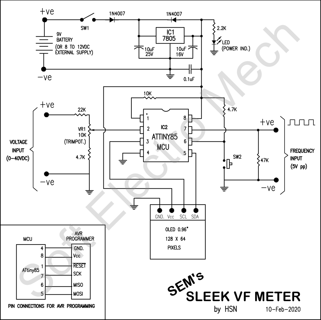
List of Important Components used in the Project:
- ATTINY85, AVR micro controller (8pin)
- OLED module, 0.96″ size, 128×64 pixels, IIC controlled (4pin)
- 7805, 5VDC output regulator IC (3pin)
- 10K trimpot
- Doides 1N4007, 1Amp capacity (or equivalent)
- Capacitors: 10uF electrolytic , 0.1uF disc capacitor
- Push button switch
- Resistances: 2.2K,4.7K, 10K, 22K, 47K 0.25W
- LED 3mm size, yellow or red
- 9V battery or other DC source
- Miscellaneous : PCB, wires, jumpers etc.
Sometimes, while measuring Frequency, the peek-to-peek voltage of the signal is also desired. The simple circuit presented here can measure DC voltage from 0V to 40V as well as Frequency of a square wave in a sleek enclosure with independent power supply option. The power supply for the circuit may be derived from a general purpose 9V battery or 8V to 12V DC power source.
ATTINY85 is eight pin MCU sufficiently powerful for the project, with 8KB flash + 512B RAM + 512B EEPROM and 1MHz default clock frequency, is heart of the system. The MCU continuously measures Voltage and Frequency through its one of the ADC pins (ADC3) and external Timer/Counter pin T0. The ADC values and Counter values are processed by the MCU and converted to Voltage and Frequency, then displayed on OLED accordingly.
OLED display is small display of 0.96” size, 5VDC supply, I2C connector, with 128×64 pixel resolution. It has 4 pins, out of which 2 for power supply, 1 for serial data (SDA pin) and 1 for the clock (SCL pin). To show text on the display, the 64 rows of pixels are divided into 8 text rows with 8 pixel rows in each text row. To display the text clearly, the code is set for 16 pixel height and 8 pixel width. So, the OLED can display text, maximum in 4 rows with 16×8 font size.
The Voltmeter of the circuit can measure and display maximum voltage up to 40Volts DC. If the voltage exceeds 40V DC, the display shows “OVER”, which indicates OVERFLOW. To protect the MCU ATTINY85, the measurement should be limited to 40V.
The Frequency Meter of the circuit can measure and display maximum up to 1MHz. For more accuracy of measurement square wave is preferred. The Peek-to-peek voltage should be about 5V for the frequency measurement. Incase of higher voltage signals, suitable voltage divider should be used with two resistors.
Working of the circuit:
When SW1 is switched ON, the 9VDC from the battery is step-down to 5VDC by voltage regulator IC 7805, which is the power supply for the MCU,ATTINY85 and OLED. All the pixels of the OLED (display) will glow for a while, as a self test and then a welcome message and delay milli-seconds for frequency measurement are displayed for a while. Then, the program enters in a loop to read frequency input at T0 pin (pin 7 of IC2) for one second (to be adjusted using the press button switch SW2), then reads voltage at ADC pin (pin 2 of IC2). The values are processed and displayed one-by-one on OLED.
Initial Setup:
Once the PCB is ready (I used general purpose PCB here), write/burn SEM_SLEEK_VF_METER.HEX to the MCU ATTINY85, using any AVR programmer and insert it to its IC base on the PCB. Otherwise, the SEM_SLEEK_VF_METER.HEX may be written to the MCU ATTINY85, using in-system programmer also.
Once, the voltage and frequency are displayed on the OLED, connect a known voltage source for testing (measured using a multi-meter) to voltage input pins, then adjust the VR1 to match the displayed voltage matches to the source voltage. Now, disconnect the testing voltage source.
Now, connect a square wave with known frequency with about 5Vpp to frequency input pins to read the frequency by the MCU and display on OLED. Incase, the frequency displayed is not matching to the source frequency, then press the button switch SW2, to increment the delay for reading the frequency, until the display shows the correct value of the frequency. This is required because the internal clock frequency is not so accurate for MCU ATTINY85, to get exact one second period. So the delay should be adjusted by trial and error method. If, the button switch SW2 is pressed at the time of welcome message, the delay value is reset to 900 milli-seconds. Again go on pressing the button switch SW2, to increment the value for accurate measurement. This process of setting has to be done once and the changed/updated value is saved into EEPROM of MCU.
To get DC power supply from the mains 230V or 110V AC for the circuit (instead of 9V battery), a 9V (250mA) step-down transformer with rectifiers and filter capacitor may be used as power-supply for the circuit.
Now, the circuit is ready for use, which can read and display DC voltage and frequency simultaneously. The OLED (display) automatically refreshes for every 15 cycles of measurement, for clearing display distortions, if any.
